
 Language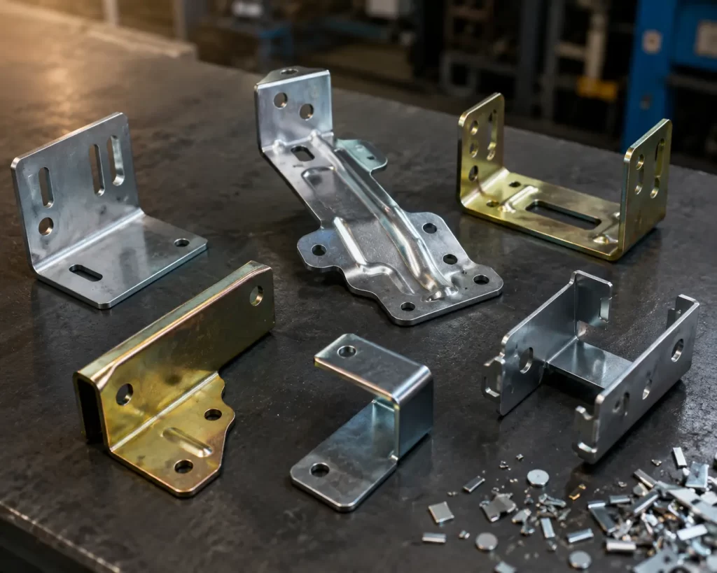
From material selection and tooling strategy to tolerance control, surface finishing, and production consistency—a practical framework for precision stamped bracket manufacturing.
Precision stamped brackets are structural mounting components produced by blanking, forming, and bending sheet metal with stamping dies. They are widely used in automotive electronics, telecommunications equipment, industrial automation, LED lighting, and medical devices for applications such as PCB mounting, sensor installation, motor support, and enclosure connections.
For engineers and procurement teams, understanding materials, tooling, tolerances, surface finishing, and high-volume quality control is essential when selecting the right manufacturing process and supplier.
What Are Precision Stamped Brackets?
Stamped brackets are commonly manufactured in L-shaped, U-shaped, Z-shaped, or more complex geometries using mechanical or hydraulic presses together with dedicated tooling.
Compared with standard stamped parts, precision stamped brackets are typically defined by three key characteristics:
- Dimensional tolerances: Critical hole diameters, hole-to-hole distances, and overall dimensions can typically be controlled to around ±0.05 mm, compared with approximately ±0.10 mm to ±0.20 mm for conventional stamping.
- Bend angle accuracy: With properly designed tooling and springback compensation, bend angle variation can be controlled within approximately ±0.5°.
- Burr control: Burr height on critical edges is typically kept below 10% of the material thickness, which is particularly important around PCBs, sealing surfaces, and precision assembly areas.
Achieving these results depends on die accuracy, blanking clearance, press rigidity, and process parameters. In practice, tight tolerances should be applied only to functional features such as locating holes and mating surfaces. Standard tolerances should be used for non-critical dimensions to balance precision with manufacturing cost.
Precision Stamped Bracket Manufacturing Process
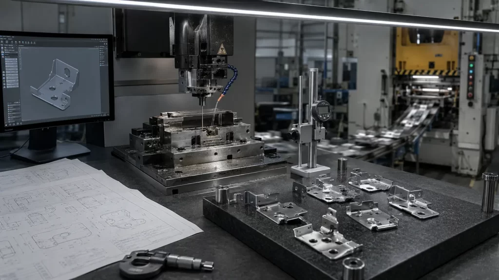
Drawing Review and Process Planning
Once the 2D drawings and 3D models are received, the first step is to evaluate bend radii, hole-to-edge distances, tolerances, formed features, and flatness requirements.
If certain dimensions cannot be reliably achieved through direct stamping alone, secondary operations such as restriking, flattening, or machining may be added.
Die Design and Manufacturing
The tooling layout is planned according to part complexity and expected production volume, including strip layout, piercing, bending, and forming sequence.
SKD11 is commonly used for medium-volume tooling, while DC53 or carbide inserts are better suited to higher tool-life requirements.
Typical die manufacturing lead time is 10–20 working days.
Tool Trial and Sample Approval
After the first tool trial, the parts are inspected for dimensional accuracy, bend springback, burr condition, and forming quality.
The tooling is then adjusted as required. Typically, 10–20 samples are supplied for dimensional inspection and assembly validation.
Production Preparation and Mass Production
Once the samples are approved, production preparation begins with material staging, incoming inspection, and First Article Inspection (FAI).
After the first article passes inspection, the project moves into mass production, followed by in-process inspection, deburring, surface finishing, final inspection, and packaging.
Material and Sheet Thickness Selection
Common Materials
| Material | Typical Grades | Key Characteristics | Typical Applications |
| Cold-Rolled Steel | SPCC, SPHC | Low cost, good formability | Industrial mounting brackets |
| Galvanized Steel | SECC, SGCC | Good corrosion resistance | Electrical and HVAC components |
| Stainless Steel | SUS304, SUS316 | Excellent corrosion resistance | Medical and outdoor equipment |
| Aluminum Alloy | AL5052-H32, AL6061-T6 | Lightweight, corrosion-resistant | LED and telecommunications equipment |
| Copper Alloys | C1100, C5210 | Good electrical and thermal conductivity or spring properties | EMI and grounding components |
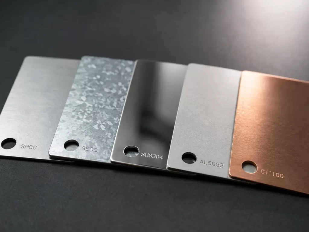
Material selection affects not only strength but also downstream manufacturing processes.
For example, SUS304 is prone to work hardening during stamping. Welding SECC requires additional consideration around the zinc coating. AL5052 offers good formability and is generally better suited to brackets with more complex bends.
How Sheet Thickness Affects Process and Cost
- 0.5–1.0 mm: Requires relatively low press tonnage and is easy to form. Commonly used for electronic brackets and shielding components.
- 1.0–2.0 mm: The most common range, offering a practical balance of strength, cost, and formability.
- 2.0–3.0 mm: Requires higher press tonnage and more wear-resistant tooling.
- Above 3.0 mm: For low- to medium-volume projects, the total cost of stamping should be compared with laser cutting plus bending.
Surface Finishing and Its Impact on Dimensions
Common surface finishes include:
- Zinc plating and nickel plating: Typically add approximately 5–15 μm per side.
- Powder coating: Typically adds approximately 60–100 μm per side.
- Anodizing: Commonly used for aluminum alloys, with typical coating thicknesses of approximately 15–50 μm.
- Dacromet / Geomet: Relatively thin coatings suitable for applications requiring high corrosion resistance while maintaining dimensional control.
- Stainless steel passivation: Produces very little dimensional change.
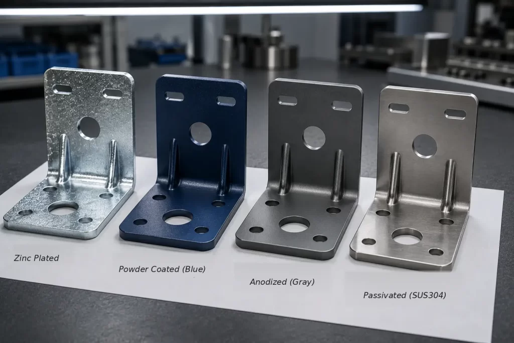
Coating thickness can directly affect assembly.
For example, an 80 μm powder coating applied to each side of a hole can reduce its effective diameter by approximately 160 μm. If the hole is intended for a precision fit, this may create assembly interference.
For this reason, mating holes, press-fit areas, and sliding surfaces may require masking, post-coating machining, or additional coating allowance in the original design.
Welding should normally be completed before surface finishing. Grounding points should also be clearly identified so that they can be masked from coating or treated with a conductive finish.
How to Choose Between Stamping, Laser Cutting, and CNC Machining
Stamping vs. Laser Cutting + Bending
Laser cutting and bending do not require dedicated tooling, making them better suited to low-volume, high-mix projects or designs that are still changing frequently.
Once production volumes reach approximately 3,000–5,000 pieces or more, stamping often becomes more cost-effective because the tooling investment can be spread across a larger quantity, reducing the unit cost.
If the part contains formed features such as ribs, embosses, louvers, or bosses, stamping offers an even greater advantage in both production efficiency and consistency.
Stamping vs. CNC Machining
CNC machining is well suited to extremely tight tolerances, complex solid features, and thicker materials. However, cycle times are longer and unit costs are generally higher.
For most sheet metal brackets in the 0.5–3.0 mm thickness range with tolerances of approximately ±0.05 mm to ±0.10 mm, precision stamping usually provides much higher production efficiency at volume.
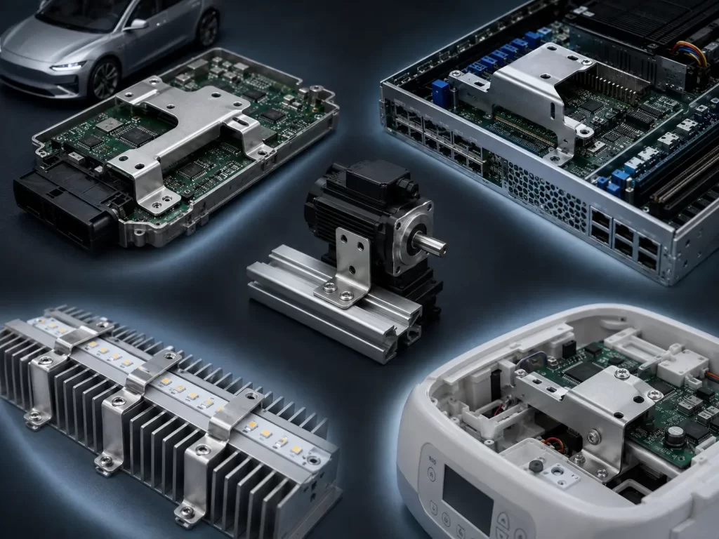
Key Applications
| Industry | Typical Parts | Common Materials | Key Requirements |
| Automotive & New Energy Vehicles | ECU brackets, sensor brackets | SECC, SAPH440 | Hole position, Cpk, production consistency |
| Telecommunications & Servers | Shielding covers, mounting brackets | SUS304, SPCC | Burr control, corrosion resistance |
| Industrial Automation | Motor brackets, connecting plates | SPCC, AL5052 | Strength, installation compatibility |
| LED & New Energy Equipment | Heat-dissipation brackets, mounting plates | AL5052, SECC | Flatness, cost |
| Medical Equipment | Internal frames, mounting components | SUS304, SUS316 | Corrosion resistance, cleanability |
What Information Should Be Included in an RFQ?
A complete RFQ helps improve quotation accuracy and reduces unnecessary back-and-forth communication.
You should ideally provide:
- 2D drawings: Including dimensions, tolerances, material, surface finish, and burr requirements.
- 3D models: STEP or IGES files.
- Material specifications: Grade, sheet thickness, and applicable standard.
- Surface finishing requirements: Process, coating thickness, color, and testing requirements.
- Estimated order quantity or annual volume: Required to evaluate tooling investment.
- Lead-time requirements: Including prototype and production schedules.
- Quality system requirements: Such as ISO 9001, IATF 16949, or ISO 13485.
- Assembly information: Helps identify critical functional dimensions.
Among these items, production volume and tolerance requirements are especially important, as they directly influence tooling design, inspection strategy, and final pricing.
How We Support Precision Stamped Bracket Projects
We begin with a Design for Manufacturability review at the drawing stage, evaluating material formability, bend radii, hole locations, tolerances, and assembly requirements. Where appropriate, we provide practical recommendations to improve manufacturability.
Once the project is approved, we can support die design, tool trials, First Article Inspection, and mass production, with in-process inspection and critical-dimension measurement used to maintain consistent quality throughout the production run.
We work with carbon steel, stainless steel, aluminum alloys, copper alloys, and galvanized steel, typically in sheet thicknesses from 0.5 to 3.0 mm. Our capabilities include progressive-die stamping, single-operation stamping, as well as secondary processes such as tapping, self-clinching hardware installation, spot welding, and hardware assembly.
For powder-coated components, pretreatment and coating thickness can be controlled according to appearance and functional requirements. Other specialized surface finishes can also be coordinated based on project specifications.
Packaging options include blister trays, separators, and protective film, depending on dimensional accuracy and cosmetic surface requirements, helping reduce dents and scratches during transportation.
Frequently Asked Questions
What tolerances can precision stamped brackets achieve?
Depending on the part geometry and tooling conditions, critical hole diameters and hole-to-hole dimensions can typically be controlled to around ±0.05 mm, while bend angle tolerances can reach approximately ±0.5°.
Which material is best for stamped brackets?
SPCC and SECC are suitable for cost-sensitive applications. SUS304 is a good choice for corrosion-resistant applications, while AL5052-H32 is well suited to lightweight parts that require good formability.
Does surface finishing affect part dimensions?
Yes. Powder coating, electroplating, and anodizing all add coating thickness. Precision mating areas should therefore be designed with the coating thickness in mind.
How long does it take to move from tooling to mass production?
Die design and manufacturing typically require 10–20 working days, followed by approximately 5–7 working days for samples and First Article Inspection. Actual lead times depend on part complexity and material.
How do I choose between stamping and laser cutting?
Laser cutting plus bending is generally the better choice for low-volume projects or designs that change frequently. Stamping usually becomes more economical and efficient when volumes reach several thousand pieces or when the part includes complex formed features.
Get a Quote for Custom Precision Stamped Brackets
We provide custom precision stamped bracket manufacturing services for global B2B customers, covering DFM review, tooling development, prototyping, mass production, surface finishing, quality inspection, packaging, and delivery.
To evaluate your project, please provide your 2D drawings, 3D models, material and sheet thickness, surface finishing requirements, estimated production volume, and critical tolerances. Our engineering team can then review the manufacturing requirements and prepare an appropriate production solution and quotation.
